Switchers
These things are everywhere. Sometimes called the unfortunate name of wall warts, but better called a DC Power Brick, or AC/DC adapter.
List
- https://www.eevblog.com/forum/projects/30w-6vdc-transformerless-psu/msg5763883/?topicseen#msg5763883 a stereo that requires a linear power supply. Someone recommends an ATX as a less noisy switcher.
- https://www.eevblog.com/forum/beginners/looking-for-information-on-tyco-se032s-module/ - tyco dc to dc switchers without any available documentation. Mentions the sync pin I will put in tips below. Uses a ucc2803 which is a unitrode (NH company bought by TI) ic.
- https://www.eevblog.com/forum/projects/wondering-about-recycling-of-electronic-power-adapters/ - About ac adapters in general, and usb c connectors. Modern switching adapters could degrade over time. While old transformer based ones are more robust (given they have less (aluminum?) electrolytics).
- https://www.eevblog.com/forum/repair/miele-elp165-s-motherboard-after-tny278gn-replacement-not-starting/ - Some troubleshooting of a TNY chip. One that doesn't use an optocoupler. Good troubleshooting guide.
- https://www.eevblog.com/forum/beginners/capacitors-before-bridge-rectifier/ - An example of high value caps (110uF) before the bridge rectifier, with opposing polarities. One of them fails. Generally a bad idea, and you can also put diodes across them to avoid reverse voltage breakdown. interesting thread.
- https://www.mdpi.com/2079-9292/14/2/391 - Evaluation Method and Modeling Analysis of the Common Mode Noise Suppression Capability of Full-Bridge Transformers
Basic Operation
- Learn Electronics Repair 16, LED Disco Lights. https://www.youtube.com/watch?v=XgPZ1XpVppE
Watch a couple dozen DiodesGoneWild videos, then refer to 9.6 of AoE afterwards. DGW is a specialist with switching power supplies and will show you actual devices, while AoE will cover the technical side (though not show PCBs).
Inductorless Switching / Charge Pump converters
AoE3 9.6.3. Useful for <100mA of current. These are integrated into other ICs at times (covered in AoE).
Calculators
TI's LM63460

Some manufacturers will have calculators in addition to the app notes that you can use. These are often based on excel/spreadsheet software. Reference: https://www.eevblog.com/forum/projects/buck-loop-stability-tuning/msg5453216/?topicseen#msg5453216 As with any spreadsheet per B. Pease (For reference, see his columns https://archive.org/details/Bob_Pease_Lab_Notes), you can only trust it if, and only if, it doesn't have any mistakes in the formulas it's built with...
TI Power Stage Designer
A useful tool to have in your toolbox. A free Windows Download. I had a set of notes on this software, let me see if I can find it...
ti's power design tool
my favorite part of the design tool, is that you can
A) pick a topology from a list
B) choose a component on the topology
C) adjust the values for the topology
D) see waveforms for the topology (on a given component) which can be adjusted with voltage and
current. interactive. intuitive. very good.
It also has a toolbox with generally useful tools.
i.e. a capacitor calculator for load transients.
rc snubber calculator for diode ringing. This one requires some measurements on the live circuit. The snubbers
for high frequency ringing are quite small (100's pf).
an output capacitor calculator. This one is simple enough, give it a voltage and wattage, and how much
power you are willing to let the rail drop, and it will give you a recommended capacitance.

It should be noted that TI's power designer tool goes well with the TI Power Topologies book (which lists
the topologies in the same order and has some additional waveforms you will expect to find).
Power 4-5-6

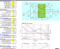
Microchip has an app note, 00002122b which details how you can use a microcontroller as a switch mode power supply controller and it has other guidelines for switch mode design. See also Amp Hour #637, where Cnlohr talks about using a micro (specifically the CH32V003) as substitutes for common dedicated chips. The image above doubles as a good checklist for a switcher circuit (in this case a flyback), detailing common parameters.
Tips/Techniques
Stock 5V and 12V
These are the most common voltages. Always try to standardize on the most common barrel plug (which is 2.1mm, and 5.5mm).
Diode Gone Wild
He has a number of videos that breakdown poorly made / falsely marketed switching power supplies and is of advanced knowledge about them. I will link some of his videos here that I found to be especially useful w.r.t. switchers.
- https://www.youtube.com/watch?v=GICw2HpsInU - 12V 0.6A flyback power supply (with schematic & waveforms). This video shows a bog standard switcher with a control chip, a TL431, an opto coupler, a couple of snubber networks, and so on. He walks through the complete functionality of the adapter. Also uses an isolation transformer to probe certain waveforms, and shows for example, how all waveforms on the transformer are identical (but at different potentials depending on the turns for a given winding). He shows clearly how the control chip is powered from a separate winding, but also first by a capacitor and connection to the main rail via the startup resistors. He shows the current sensing resistors on the source of the control chip's internal mosfet. Additionally, he shows how the TL431 is powered by a resistor, even when the opto coupler is off, but still being on the same rail/trace. The voltage divider for the TL431 can also be spotted (that is used to signal the chip to power on the opto coupler when at, I think 2.5V). The adapter in this video is used for a AA/AAA battery charger.
- https://www.youtube.com/watch?v=919KTlZKLcY - 12V 1A wifi router adapter test and analysis. Another good switcher diagnosis. This particular switcher omits some components, but may still pass EMI due to some other component choices, and it runs to 1A without failure.
Example of 5V 8-pin DIP Regulator
https://www.eevblog.com/forum/repair/need-help-to-identify-a-blown-chip-in-skynet-for-z12c-switching-power-supply/msg5445107/ It's always easy to spot the capacitor and diode.
Sync Pin on DC to DC converters
To get better power rail stability, and to reduce EMI, it's possible to either sync multiple DC - DC converters up, or have a power governor that controls when each one draws current. The sync pin requires a clock (pulse) input. The laurent article also goes into how the capacitors impact the power rail stability, proposing using a NOT gate to get a 180 phase shift on the clock from one converter to another. It also discusses ESR and its effect on limiting capacitance response.
http://betadynepower.com/wp-content/uploads/2017/11/Synchronization.pdf